In the last part of this series we talked about getting the GPU to do some work by transferring images to the video memory and displaying that on the screen.
Note that the images in that case were still generated in the CPU, and then sent over to the GPU, the only action taken by the GPU in this configuration was displaying the “precompiled” images on the screen.
 call")
The next step is to actually make the GPU itself draw to the screen, after all that’s its main functionality!
The Goal
We know we want to send commands to the GPU in this part… but which
commands? For now we will settle in sending commands to fill random rectangles
in the screen with random colors. Our final program will just go on filling
rectangles to the screen (or actually, making the GPU do it) endlessly until we
tell it to terminate with CTRL-C.
Command Batches
How are commands actually sent to the GPU? Do we just generate a big array with all commands one after another and send all of that?
The answer to that is, yes, that’s exactly what we do. Just like everything
else, there is one ioctl() syscall for sending commands to the GPU
(DRM_IOCTL_I915_GEM_EXECBUFFER2), and that is exactly what we use to make it
draw something on the screen. There are just two smaller details that need to be
handled first: contexts and relocation.
We will start with relocation since it’s the more important one. For more details on how the intel GPU works with commands, check this nice section in the i915 kernel documentation.
Relocation
One of the jobs of the graphics card driver is to make sure that when it tells the GPU:
read a value from this memory location
the memory location is an actual position in the VRAM accessible to the video card. You can’t go telling it to read from anywhere in the userland memory. So, what does the driver do? It keeps a translation map of where in the video memory things are, and handles pointing to them. This way you can just specify the handle and the driver knows the actual memory location, resulting in a translation of this sort:
- userland says “read a value from ____, but please fill in the blank with this handle”
- driver translates to “read a value from this memory location”
- driver sends that to the GPU
Contexts
Contexts, as the i915 driver documentation says, work like processes in a operating system, in our case making sure that commands are executed in sequence and the later ones wait for the earlier ones to finish before executing.
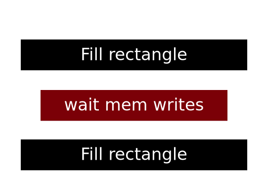
That little block in between the “fill rectangle” commands is what is provided
by the context, making sure all the data is written before we move on to filling
the next rectangle. If we try to execute without a context (we certainly can!)
there would be a lot of corruption because the graphics card can execute
many such “fill rectangle” commands at the same time thanks to its many
cores, or, as intel calls them, EUs: Execution Units.
Contexts also make sure that the state of the GPU is saved and restored when switching to different contexts, so if we have two contexts for doing two different things, when we switch back and forth each context will have it’s own state which things done in the other contexts will not affect.
As with everything, they are created via a ioctl() call with
DRM_IOCTL_I915_GEM_CONTEXT_CREATE and a custom kernel struct. But there is a
nice wrapper around the kernel API in libdrm: drm_intel_gem_context_create().
In the end, all we need is to call drm_intel_gem_context_create(), which will return a context and later use another function to execute our commands in our context, making sure they run sequentially.
Draw Loop
And now I think we are ready to jump in and start coding something! The first thing we will do is setup an infinite loop for drawing our rectangles, and start it after finishing our mode setting (check Part II):
// KMS (mode setting)
assert(drmModeSetCrtc(gpu, controller->crtc_id,
                        buf_id,
                        0, 0,
                        connector_ids, 1,
                        &connector->modes[m]) == 0);
// Start the loop, passing in pointers to the framebuffer and its size
draw_loop(gpu, bufmgr, screen, width, height);
The actual loop will be something like:
void draw_loop(const int gpu,
               drm_intel_bufmgr* bufmgr,
               drm_intel_bo *screen,
               uint32_t width, uint32_t height) {
  // Create a context that will be used to execute commands
  auto context = drm_intel_gem_context_create(bufmgr);

  while (/* detect a ctrl-c */) {
    // ... tell the GPU to draw a rectangle ...
  }

  drm_intel_gem_context_destroy(context);
}
Now, just to make coding a bit more confortable, lets design a struct that will hold all information relevant to drawing to the screen so we can pass it around to functions which will actually send the commands to the GPU.
// Put everything needed to draw to a framebuffer (i.e.: the screen) in one
// place so we can easily pass everything around.
struct intel_drawing_context {
  // Keeps track of where to send the ioctl() calls to
  const int gpu;
  // Keeps state for the vram memory allocator
  drm_intel_bufmgr *bufmgr;
  // Keeps track of the current "process" inside the graphics card to execute
  // commands
  drm_intel_context *gpu_ctx;
  // This is the actual buffer containing the pixels in the screen
  drm_intel_bo *buffer;
  // The pitch for the screen buffer (i.e. width * bytes per pixel)
  const uint32_t pitch;
};
And, in draw_loop(), after we create the context (but before entering the
while) lets initialize one of those intel_drawing_context struct:
// Build a drawing context to draw things on
struct intel_drawing_context ctx = {
  .gpu = gpu,
  .bufmgr = bufmgr,
  .gpu_ctx = context,
  .buffer = screen,
  .pitch = width*4+32
};
Now, inside the loop, lets generate a random position and size for our rectangle to be drawn:
while (/* detect a ctrl-c */) {
  const uint32_t x = rand()%width, y = rand()%height;
  const uint32_t w = rand()%width, h = rand()%height;

  // ... tell the GPU to draw a rectangle ...
}
Now we pretend we have a function to draw the rectangles already and call it. We
pass it the intel_drawing_context we just created above, called ctx. We pass
it the position and size of the rectangle, and also another uint32_t, which
will also be random, representing the color of that rectangle (red, green, blue
and alpha components all together, 8bits for each).
while (/* detect a ctrl-c */) {
  const uint32_t x = rand()%width, y = rand()%height;
  const uint32_t w = rand()%width, h = rand()%height;

  intel_2d_rect(ctx, x, y, w, h, rand());
}
And now we have to somehow implement this intel_2d_rect() to send the correct
commands to the GPU. Before we do that, lets talk a bit about the format of
such commands.
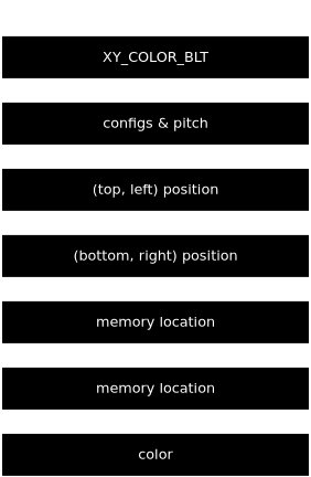
Command sequences for intel graphics cards are made out of 32bit blocks. They start with a block telling what the GPU should do, followed by more 32bit blocks containing the data for that instruction: positions, colors, memory locations, configurations and anything else needed.
In a single command sequence we can have more than a single command, so all of that can be followed by another 32bit block specifying another command, more data and so on. After all the commands we have a special block, specifying that the command sequence has ended.
So, how do we find the 32bit numbers that should be sent then? In the intel
documentation pdfs. We are using the one for Skylake processors
in this series. The file which contains the data on the instructions we are
using is intel-gfx-prm-osrc-skl-vol02a-commandreference-instructions.pdf.
The instruction we are interested in sending is the XY_COLOR_BLT, which fills
a rectangular area of the framebuffer with a color.
We will #define the number associated with it and some of its configurations
at the start of our program:
#define CMD_MI              (0x0 << 29)
#define CMD_2D              (0x2 << 29)
#define XY_COLOR_BLT_CMD    (CMD_2D | (0x50 << 22))
// Configurations for XY_COLOR_BLT_CMD
#define XY_BLT_WRITE_ALPHA  (1 << 21)
#define XY_BLT_WRITE_RGB    (1 << 20)
// Terminate a commands buffer
#define MI_BATCH_BUFFER_END (CMD_MI | 0xA << 23)
The we can create a array containing everything needed for XY_COLOR_BLT to work, plus that special value to tell the GPU the sequence of commands has ended:
{
  // 0x5 is the command length
  XY_COLOR_BLT_CMD | XY_BLT_WRITE_ALPHA | XY_BLT_WRITE_RGB | 0x5,
  // pitch and some configurations
  (0 << 30) | (0b11 << 24) | (0xf0 << 16) | ctx.pitch,
  // top-left
  (y << 16) | x,
  // bottom-right
  ((y+height) << 16) | (x+width),
  // memory address to write to
  0,
  0,
  // color to use
  color,
  // sequence of commands has finished
  MI_BATCH_BUFFER_END
}
Notice we did not put anything in the destination memory address (the address
the GPU is supposed to write to). That’s because relocation will take care of
filling that in. We just need a way to inform the handle. Lets pretend for a
second we have a function that takes our array of commands and a list of
relocations needed and does it for us, then our intel_2d_rect() could be:
void intel_2d_rect(struct intel_drawing_context& ctx,
                   uint32_t x, uint32_t y, uint32_t width, uint32_t height,
                   uint32_t color) {
  send_blt_commands(ctx, {{4, ctx.buffer}}, {
    XY_COLOR_BLT_CMD | XY_BLT_WRITE_ALPHA | XY_BLT_WRITE_RGB | 0x5,
    (0 << 30) | (0b11 << 24) | (0xf0 << 16) | ctx.pitch,
    (y << 16) | x,
    ((y+height) << 16) | (x+width),
    0,
    0,
    color,
    MI_BATCH_BUFFER_END
  });
}
The second argument to send_blt_commands() is a list of pairs containing an
index in the command buffer (in 32bit increments) and a buffer object.
send_blt_commands() will be responsible for fetching a handle from each of
those buffer objects and telling the driver to write the correct memory position
for that handle in the command buffer position specified by the index. In our
case this means replacing the 0, 0 part of the commands with the vram memory
address of ctx.buffer, which is the screen.
Okay, cool, so now we just need to implement this magic send_blt_commands()
function!
This is its source in full:
void send_blt_commands(struct intel_drawing_context& ctx,
                       std::vector<std::pair<size_t, drm_intel_bo*>> refs,
                       std::vector<uint32_t> commands) {
  // Convert the number of commands to the length of the command buffer in bytes
  const auto length = commands.size()*sizeof(uint32_t);

  // Create the buffer
  auto cmds_bo = drm_intel_bo_alloc(ctx.bufmgr, "commands", length, 0);

  // Map to memory, 1 = writable
  // and write the commands to it
  drm_intel_bo_map(cmds_bo, 1);
  memcpy(cmds_bo->virt, &commands.front(), length);
  drm_intel_bo_unmap(cmds_bo);

  // Setup all addresses referenced
  for (auto ref: refs) {
    // For each address update the original command buffer with the actual
    // memory address of the referenced buffer object
    assert(drm_intel_bo_emit_reloc(cmds_bo, ref.first*4,
                                   ref.second, 0,
                                   I915_GEM_DOMAIN_RENDER, I915_GEM_DOMAIN_RENDER) == 0);
  }

  assert(drm_intel_gem_bo_context_exec(cmds_bo, ctx.gpu_ctx, length, I915_EXEC_BLT) == 0);

  drm_intel_bo_unreference(cmds_bo);
}
We start off by creating a buffer object containing the same data as the
commands vector we received. Then we use drm_intel_bo_emit_reloc() to create
all the relocations from the refs vector. Finally we call
drm_intel_gem_bo_context_exec to execute our newly created buffer in the
context we created earlier. Notice we also use the I915_EXEC_BLT constant
there, to execute the command buffer in the “blitting” engine. This is needed
because intel cards have multiple different “engines” with different purposes,
which accept different types of commands. For our XY_COLOR_BLT, the engine
which supports it is the blitting engine.
Results
We are done! Compile with:
❯ clang++ drm-part-3.cpp -o drm-part-3 -I/usr/include/libdrm/ -ldrm -ldrm_intel
And when we run…
❯ ./drm-part-3
Success! We are controlling the GPU!